Using Heat Treated Carbon Fiber HTPLA for the Prusa MK3 R3 Extruder Assembly
Many times when printing extruder assembly parts for a 3D printer, like the R3 extruder upgrade for the Prusa MK3, PETG or ABS are specified as the material to use due to the heat exposure. However, Carbon Fiber HTPLA works great in these cases because of the carbon fiber's ability to hold form (rigidity), printed part detail, and heat resistance. Add to that the beautiful finish of 3D printed carbon fiber and even a function-before-form guy like myself gets excited.

So where does HTPLA's heat resistance come from? It comes from it’s semi-crystalline structure. Amorphous materials like PETG and ABS surrender their stiffness (and thus form) at glass transition (Tg), about 80 and 105 deg C, respectively. HTPLA's Tg is even lower at about 55 deg C, but HTPLAs are semi-crystalline (part amorphous and part crystalline).
When amorphous, HTPLA looses stiffness at about 55 deg C, but heat treating HTPLA transforms the material structure from mostly amorphous to partially crystalline. Crystalline structures retain useful stiffness up towards their melting temperature which for HTPLA is about 170 deg C. With HTPLA on your PLA printer you can make a part that'll survive a hot car or be near a printer hotend without the fumes and difficulties of ABS.
When heat treating HTPLA, people are generally nervous about the fact that a part changes size during the heat treating process and can even distort. Scaling or size change is minimized significantly from around 2-3% with translucent HTPLA down to around 0.6% with Carbon Fiber HTPLA. Additionally, Carbon Fiber HTPLA experiences little to no distortion during heat treating alleviating the concern of warping. So, let's try this with the MK3 R3 extruder parts and see how it turns out.
First, we scaled the parts based on the percentage of change expected in each axis. In the Heat treating Carbon Fiber HTPLA for accurate, heat resistant parts post we found sample scales of 100.6% for x and y and 99% for z. Notice we scaled up 0.6% for the axis that will shrink and down 1% to compensate for the expansion in z. These scale factors were applied to parts in the slicer. Parts were then sliced and printed. For the print the following settings were used (Settings are provided as information only - do not fixate on these values as they are not essential to success) :

- 0.15 layer
- 3 perimeters
- 3 top/bottom layers
- 35% infill
- 55mm/s
- 220C nozzle
- 55C heated bed
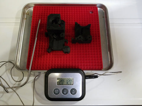
After the parts were printed, we heat treated them in an oven. The parts were placed in the oven for 30 minutes at 100C and then allowed to cool within the oven. Note the alarm temp of the thermometer is 120C in the picture. This is to warn in case the oven spikes, it is not the temp the oven was set to. Again the time and temp used are not critical so don't fixate on these exact values.
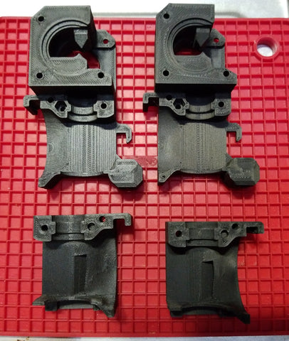
After the parts were allowed to cool in the oven, we took measurements to check our results. The picture below shows the scaled then heat treated parts on the right and printed parts with no scale applied on the left . The part in the lower right corner may look smaller than its counterpart to the left but that's actually you're eyes playing tricks on you (or my bad photography). The 39.5mm parts are actually only 0.2mm different in length.
Notice the lack of sheen or shine on the heat treated parts? This is one of the best ways to know your part has been heat treated. Heat treated PLA becomes more opaque and also loses some sheen as a result.
To check that our parts scaled as expected during the heat treating process we compared the measurements of the heat treated parts to those that were printed with no scale. Additionally, we checked those numbers against the design dimensions to see how close the results were to the actual desired size. As you can see in the table below the heat treated part came out pretty accurate. And compared to the printed part with no scale was similar in accuracy as a part that hadn't been heat treated.

But of course, the real test is how well does it actually fit. What do you think?


As you can see things fit together real well. Ready to give heating treating Carbon Fiber HTPLA a try?
Just a few notes as we wrap this up because there is a bunch of material to digest in this write-up.
How do you know how long to heat treat? Or when is my heat treating done?
A good starting point for heat treating is 15-30 minutes at 100-120 deg C. Thinner parts will heat treat faster and thicker will need more time. Also the higher the temp the faster the part will heat treat. There is some art to this and will take a bit of trial and error to find what works best.
The best during heat treating indicator for completeness is the color change. Heat treated HTPLA becomes more opaque and has less sheen. Measuring the size change is another way, but this requires letting the part cool as a warm part will measure larger than a cool one due to thermal expansion. Also, working with a warm part can introduce distortion or burn you.
How accurate are the scaling factors? Will they work for me?
Our scale factors were developed on a Prusa MK3 by printing generic test bars in each axis (more details here). In contrast, the extruder parts in this write-up were both a different shape/size and printed on a Zortrax M200 using the scaling factors found on the MK3. Still, the printed parts fit well together and matched up well with the other printed and non-printed parts of the MK3 extruder assembly. We printed non-scaled parts so we could compare to a typical printed accuracy of the Zortrax M200.
The scales aren't perfect, but either are the printed parts without scaling or heat treat. We found the entire workflow gave a typical and acceptable accuracy level. With more work, could parts could be more accurate? Sure, but that doesn't seem necessary. Minor changes could improve the accuracy of your prints or printer.